Project Development
PROJECT SUMMARY
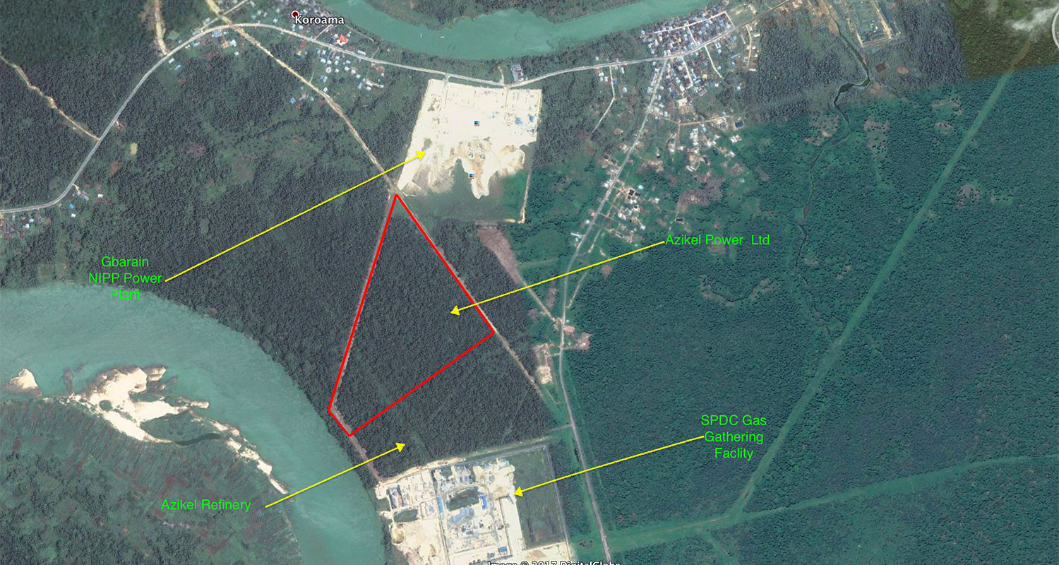
Azikel Power’s 500 MW capacity, natural-gas-fired plant is being engineered to generate power by receiving its gas supply from the existing Nigerian Gas Company pipeline that was designed to carry 78.17 MMSCFD of gas through a 20m-long proposed pipeline from the neighboring Shell Petroleum facility to the proposed project site.
Azikel Power’s 500 MW capacity, natural-gas-fired plant is being engineered to generate power by receiving its gas supply from the existing Nigerian Gas Company pipeline that was designed to carry 78.17 MMSCFD of gas through a 20m-long proposed pipeline from the neighboring Shell Petroleum facility to the proposed project site.
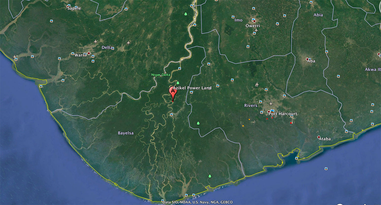
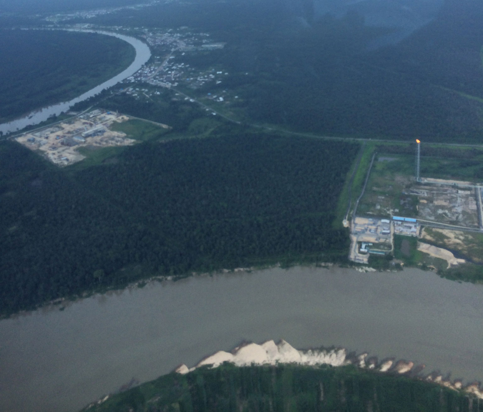
The project site is located near Obunagha village, Yenagoa town in Bayelsa state of Nigeria.The town of Yenagoa is about 20 Km from the project site, whereas the major city of Port Harcourt is about 100 Km away. The nearest railway station and the nearest airport also are located about 100 Km away at Port Harcourt. The Latitude and Longitude are 05° 01’ 21.9’’ N and 06° 17’ 42.155’’ E, respectively.
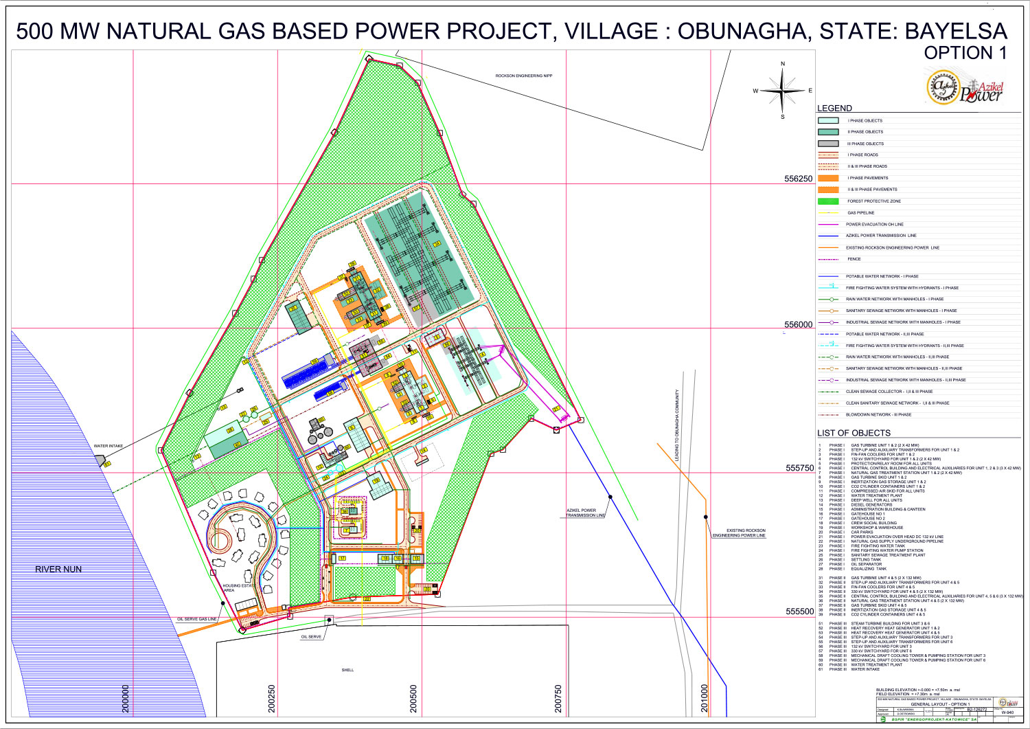
Azikel Power is establishling the 500 MW power plant in three phases as outlined below:
Phase 1: Simple Cycle: 2 x 38 MW – heavy-duty GT (frame 6 engine) = 76 MW
Phase 2: Simple Cycle: 2 x 125 MW – frame 9 engines GT = 250 MW
Phase 3: Combined Cycle: 2 HRSG + 2 ST = 38 MW ST+125 MW ST = 163 MW
It is designed to generate power using natural gas procured from the existing pipeline of Nigerian Gas Company through a separate 20m-long gas pipeline that will carry 78.17 MMSCFD of gas from the Shell Petroleum Facility to the proposed site, fulfilling the overall natural gas requirement. Another 10m pipeline for heavy oil also will be supplied from the Azikel Refinery site.
The plant’s water as required for cooling will be taken from the Nun River, which flows alongside the project boundary. The cooling system is designed to improve the performance of the condenser and plant output, but it requires a large quantity of water – approximately 25,000 m3/hr. For the Phase 3 Closed Circuit, two induced draft cooling towers will be used.
Azikel Power has acquired 80 acres of private land for this project, and has conducted the topographical survey. The project components, such as GTs, HRSGs, STs, and auxillary components will require 55 acres of land; the remaining 25 acres will be used for greenbelt development around the project boundary to isolate the site.
OUR TECHNOLOGY
The Power Plant Phase 1 and Phase 2 utilize a gas turbine option. The gas turbine will be a heavy-duty unit, single shaft, with inline compressor and direct-coupled generation. It will be equipped with an advanced combustor and will be characterised by high-reliability efficiency. The available gas turbine is as follows:
Phase 1: 35-45MWe
Phase 2: 115-135MWe
The power plant, in its final design, will consist of multi-shaft units. The units will be based on two heavy-duty gas turbine generators and auxiliary facilities in a 2+2+1 configuration. The plant configuration will be based on technical standard solutions designed by the future contractor to meet requirements of the company and project specification.
Phase 3 will be built as a combined circle, which will primarily use steam to generate the desired power balance. This is illustrated below:
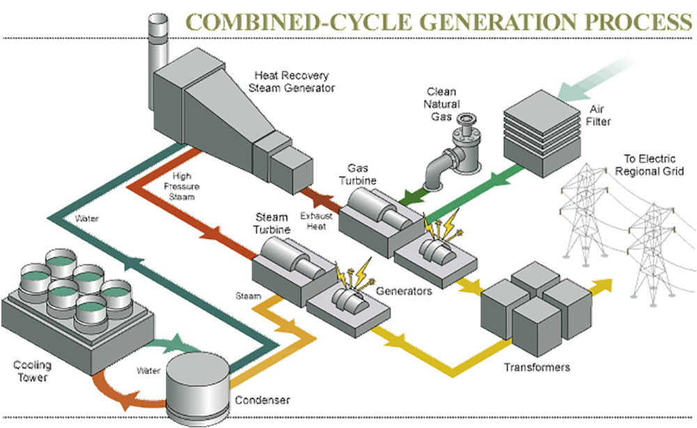
Due to the fact that the exhaust gas temperature at the outlet of the gas turbine is very high, the overall thermodynamic cycle efficiency is relatively low. The efficiency of chemical energy from fuel increases with the combined gas-steam system. The exhaust gas from the gas turbine is directed to a heat recovery steam generator that produces steam, which expands in a steam turbine. The combined-cycle will improve the efficiency from approximately 30% (simple cycle) to approximately 50% – 60%. Steam produced in the HRSG is directed to a steam turbine, which drives the electricity generator for an additional source of electricity.
The cooling systems are designed to be open circuit. Water for cooling purposes is collected in the water intake facility and flows through mechanical cleaning system. The water is directed to the turbine condenser.
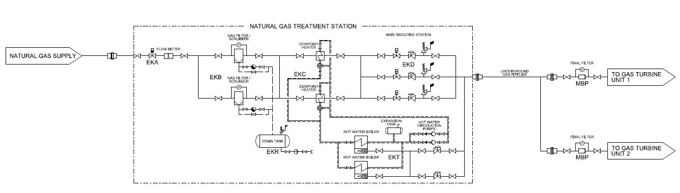
FUEL GAS SUPPLY
The facility will be supplied to the battery limits by a DN 300 pipeline. The gas will be directed to the natural gas treatment station, which will provide adequate gas parameters in all operating conditions. From the gas treatment station, fuel will be transported by underground pipelines to the gas turbine area.
USE OF WATER RESOURCES
Combined-cycle plants require more water than peaker plants. Typically, in combined-cycle facilities such as the one planned for Azikel Power, the water flows through the cooling process multiple times to minimize water use. Water for the plant will be sourced from the Nun River. The distance between the river and the site boundary is about 40m – 50m.
The water from River Nun will serve for production of:
- Clarified water – makeup water for the closed cooling system. The sewage, after the appropriate treatment, will be discharged back to the river, taking into consideration the required wastewater quality. (Until the construction of the steam of the system, the power plant water demand will be covered by the underground water from deep wells only.)
- Potable water
- Demineralized Water – makeup for the dry closed cooling circuit/makeup for the steam cycle/GT compressor washing
POWER EVACUATION
The electric power from the first two GT generators and corresponding ST generator will be evacuated using step-up transformers to the new air-insulated 132kV substation “AZIKEL 1.” That substation will be connected with the 132kV “YENAGOA 1” substation through a 3km-long double-circuit overhead line. The plant’s auxiliaries will be fed from a 2-unit auxiliary transformer. Black start will use energy from an emergency diesel generator.
Power generated from the 9E machines and STs (Phase 2 – 3) will be evacuated through step-up transformers to the new air-insulated 330kV substation “AZIKEL 3.” The substation will be connected with a future 330kV overhead double power line “ONNE-DELTA IV.”
For information on Azikel Power, please contact us at (+234) 8103444440 or (+234) 8101002227. Email info@azikelgrp.com.